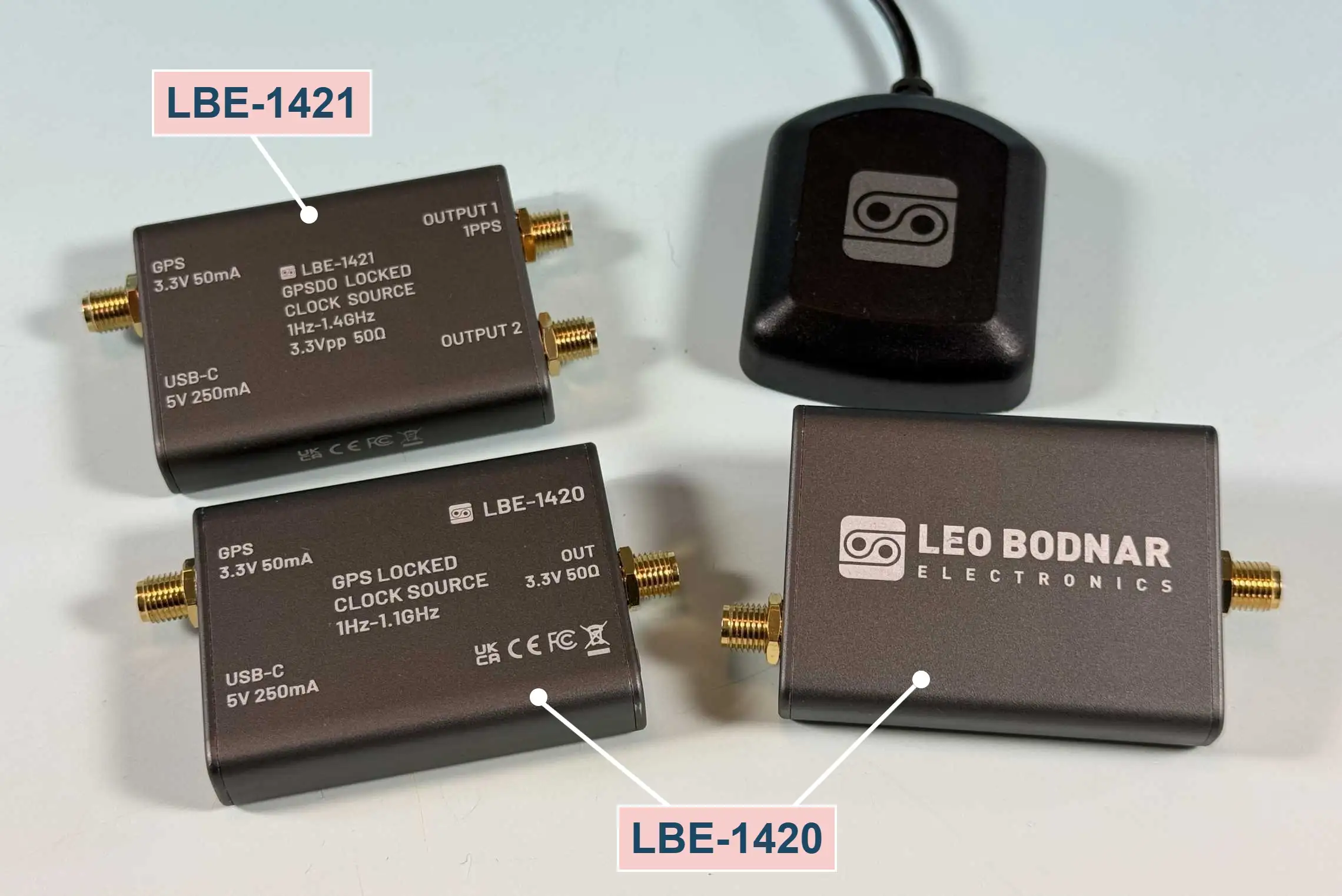
This guide covers the output options, FLL vs PLL mode, which satellite systems to enable in the UK, and the dynamic model, finishing with suggested settings you can copy when setting your GPSDO up as a reference or local osillator for your transverter. The examples I provide use the LBE-1421 software, which has two outputs; the LBE-1420 has a single output. Software for each of these GPSDOs can be found on the respective pages of the Leo Bodnar Electronics website.
Output Settings
Frequency output
Each output has a frequency box and a Set button: enter the frequency you want in Hertz and press Set. On the LBE-1421, OUT1 covers 1 Hz to 800 MHz and OUT2 covers 1 Hz to 1.4 GHz, both as 3.3 V CMOS square waves. A common choice is 10 MHz on one output, with a second frequency (such as 100 MHz in my example) for other equipment. Set each output to whatever your transverter or other equipment expects as its reference or local oscillator.
Low power
Each output has its own Low power checkbox. Ticking it reduces the output level on that port to about +1 dBm, compared with roughly +11 dBm at 10 MHz without the box being checked. A lower level suits some equipment. Always check the recommended input drive level range for your transverter and stay within it.
1 PPS
Ticking 1PPS switches OUT1 from a continuous frequency to a one-pulse-per-second timing signal derived from GPS. It replaces the frequency output on that port, although OUT2 on the LBE-1421 continues to supply a frequency. For a transverter reference, leave it unticked. It is useful if you want to synchronise a frequency counter, or other timing equipment. Note that with FLL enabled (see below), the output phase is not locked to GPS, so the 1PPS pulse and your frequency outputs shouldn’t be assumed to stay phase-aligned.
NMEA
NMEA is the standard text format GPS receivers use to report position, time and satellite status. Leo Bodnar describes OUT1 as able to serve alternatively as a 1PPS or NMEA output, so ticking this option makes the unit supply this data for other software or equipment to read. It isn’t needed for frequency-reference use, so leave it off unless you have a specific use for the data.
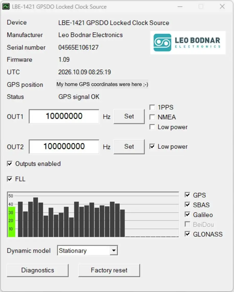
LBE-1421 Software Screen showing the output settings
FLL vs PLL Mode
Most modern GPS-disciplined oscillators, including the Leo Bodnar LBE-1420 and LBE-1421, offer a choice between PLL (phase-locked loop) and FLL (frequency-locked loop) disciplining modes in the software. This setting matters more than the naming suggests, and picking the wrong one can quietly degrade a microwave station’s local oscillator.
In PLL mode, the GPSDO disciplines both the frequency and the phase of its output to the GPS reference, keeping the output’s zero-crossings aligned to the GPS 1PPS signal. This gives excellent absolute phase and timing accuracy, which is essential for applications like NTP/PPS timing distribution or time-of-arrival measurements. The cost is that maintaining phase lock requires periodic small phase-correction steps, which appear as tiny glitches in the output’s short-term frequency stability — a worse Allan deviation (ADEV).
FLL mode disciplines frequency only. It steers the oscillator to match the GPS-derived frequency over time but makes no attempt to correct phase, so the output’s phase is allowed to drift freely. Without phase-correction steps interrupting it, the output frequency is smoother on short and medium timescales, which shows up as a better ADEV curve. The trade-off is that the oscillator’s absolute phase relationship to UTC is no longer maintained, so it is unsuitable for any application that depends on time or phase alignment.
Phase Noise Multiplication
For microwave transverter local oscillators, this trade-off favours FLL. Any phase noise or phase steps in the reference are amplified by 20·log₁₀(N) dB, where N is the multiplication factor. At microwave bands this factor can easily reach 100 or even more, meaning a modest phase correction at the reference frequency can become an audible click, a momentary frequency jump, or a spectral spur once multiplied up. This can affect narrowband, weak-signal work — SSB, CW, digital modes, where a clean, glitch-free carrier matters far more than absolute phase alignment to GPS time, which a transverter reference has no use for in the first place.
So, for a transverter or other pure frequency-reference application, enable FLL mode for a smoother, spectrally cleaner LO. Keep PLL mode for applications that genuinely need phase or time synchronization, such as 1PPS timing distribution, NTP servers, or time-difference measurements.
Which GNSS Constellations to Enable in the UK?
Many GPSDOs, including the Leo Bodnar LBE-1420 and 1421, allow the receiver to track more than one satellite system. In the UK the available options typically include GPS, GLONASS, Galileo, and SBAS, and it’s worth understanding what each contributes before deciding which to enable.
GPS (United States) and GLONASS (Russia) are both full global constellations and are well covered across the UK. Galileo, the EU’s constellation, is also a complete global system; its open civilian signal is freely usable by any standard receiver, even though the UK lost access to Galileo’s encrypted government service after Brexit. SBAS is different in kind — rather than a full constellation, it is a regional augmentation service that uses a small number of geostationary satellites to broadcast differential corrections and integrity data, primarily to improve position accuracy for aviation and other safety-critical users. In Europe this is EGNOS, and while the UK’s certified safety-of-life EGNOS service ended after Brexit, the open signal is still broadcast and receivable, with a UK-specific SBAS replacement currently in trials.
For a fixed installation such as a transverter reference, enabling GPS, GLONASS, and Galileo together is generally worthwhile. Tracking more satellites across multiple constellations improves the receiver’s satellite geometry, giving a more robust and continuous fix, faster reacquisition if the antenna’s sky view is briefly obstructed, and resilience against an outage or local interference affecting any single constellation. Modern GNSS receivers, including the u-blox modules commonly used in these units, handle the timing offsets between constellations accurately, so combining them introduces no meaningful risk to frequency or timing performance in a stationary application.
SBAS is less relevant here. Its main benefit — differential correction of position — has little value for a fixed-site reference that isn't solving for a moving position. It can safely be left enabled, since it simply adds a couple of extra geostationary satellites to the tracking pool, but it shouldn't be expected to improve frequency accuracy the way a full additional constellation does. The practical recommendation is to enable GPS, GLONASS, and Galileo for the most robust fix, and treat SBAS as optional.
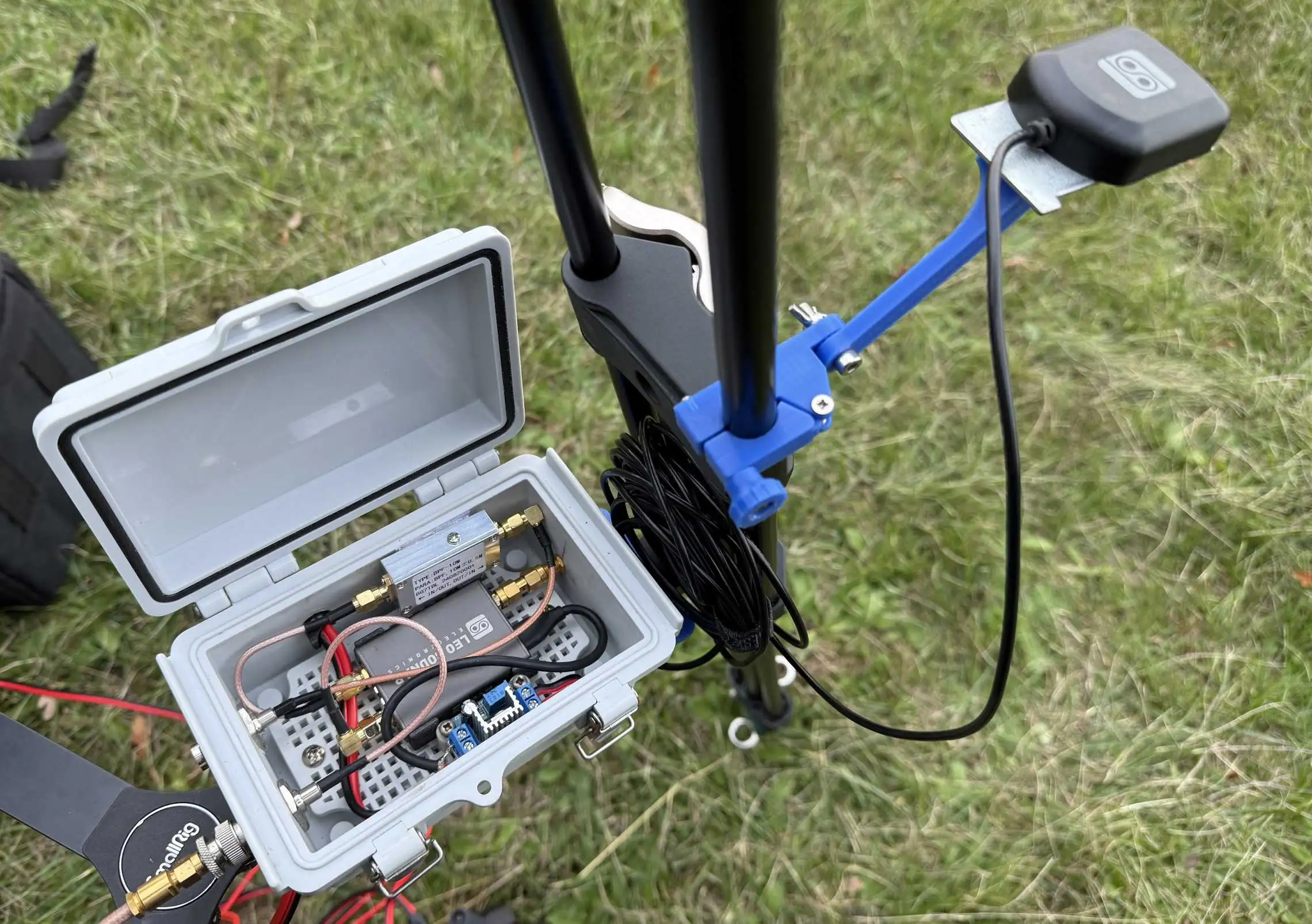
My portable GPSDO for 10MHz Reference and 106.5MHz Local Oscillator for a 10GHz transverter mounted on my tripod.
Dynamic Model
The Dynamic model setting tells the GNSS receiver how the antenna is expected to move while the unit is powered, which affects how heavily it filters its position and timing solution. The choices are Stationary, Portable and Airborne. The names can mislead amateur operators: “portable” in the receiver means the antenna is moving about, as when walking or travelling in a vehicle. It does not mean you are operating portable.
If you set up on a hilltop, for example during a contest to operate for a few hours, then pack up and move back home, the antenna is stationary the whole time the GPSDO is in use, so Stationary is the correct choice. That setting allows the tightest filtering and gives the most stable timing and frequency discipline. Choose a more dynamic model only if the unit is powered and in use while the antenna is actually moving.
Airborne is intended for fast, high-acceleration movement such as aircraft and should never be needed for most amateur operation. Choosing a more dynamic model than you need makes the receiver more willing to accept sudden changes in its solution, which can add noise.
Suggested Settings for a Transverter LO or Reference
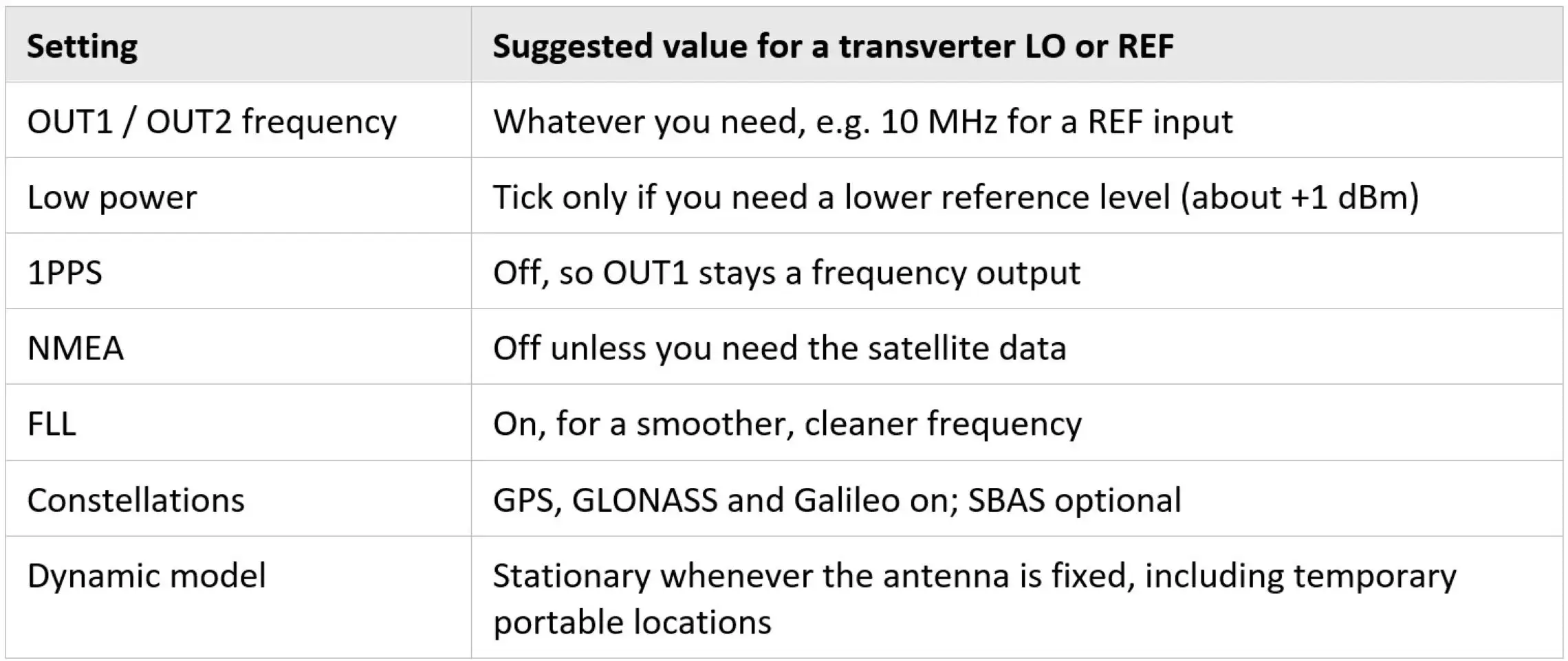
Putting these setting all together, here are some sensible starting values for a GPSDO used as the Local Oscillator or reference frequency for a microwave transverter:
A Note on DC at the Outputs
The LBE-1420 and LBE-1421 outputs are 3.3 V CMOS square waves, so the signal swings between roughly 0 V and 3.3 V and carries a DC component of about 1.6 V on top of the RF. Most transverters have a DC-blocking capacitor on their reference input, in which case there is nothing to worry about. Don’t assume this, though, especially with home-built or modified equipment. A DC-coupled input can upset the bias of the first stage or be overloaded by it, and a DC path to ground could load the GPSDO’s output stage (although Leo notes that they are tolerant of this). Check your transverter’s schematic or documentation, or measure the input with a multimeter with the reference disconnected, to see whether it has a series capacitor. If it does not, or you are unsure, fit an inline SMA DC block between the GPSDO and the transverter or filter if you are creating a sine wave. Check that the DC block’s specified low-frequency limit is comfortably below your reference frequency, as some are only specified from 10 MHz or higher. Alternatively, build a lead with a series capacitor of around 10 nF to 100 nF. Also avoid connecting the output to anything that supplies a DC voltage, such as a bias tee.