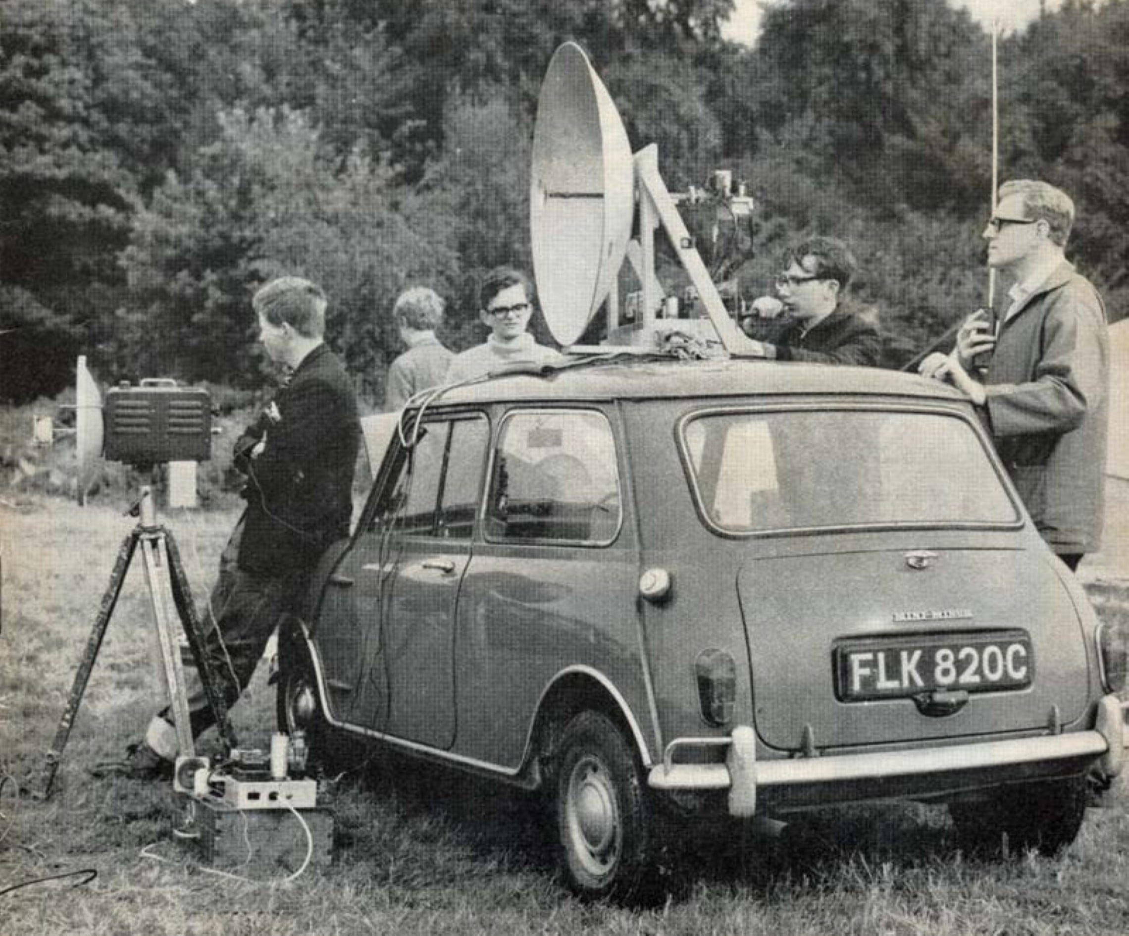
Above, taken from the cover of the October 1968 Radio Communication magazine. The caption reads: In VHF National Field Day, the Purley and District Radio Club successfully set up a 3 cm (10,000 MHz) microwave station. Most of the equipment was constructed by G8ASV (operating the equipment behind the large dish), and runs a 723A/B klystron. The member on the right is G3WDY. Photo courtesy of the Microwave Museum / G8LSD
Introduction
This article is based on Peter Day’s original history of 10 GHz amateur microwaves, published on his website. Peter, G3PHO, has kindly given me permission to republish it. Most of the history and the first-hand experience are his. I have edited some text, standardised the technical terms, brought the story forward from 2020 to the present day, and added some additional photographs and information where I could find it.
I am also very grateful to Clive Elliott, GW4MBS, who has shared his own recollections of 10GHz in the UK, in two articles and a series of emails with me. Wherever the text draws on his articles or emails, I have said so with phrases such as "As Clive GW4MBS recalls", and his work is listed in the references.
In the beginning
In the UK at least, 10 GHz is probably the most popular of the amateur microwave bands. It has about sixty years of development behind it, starting with the first experimental contacts made by W2RJM and W2JN in the USA in 1946. They could hardly have known what would follow their 2 mile (3 km+) contact. In 1947 the world 3 cm record was extended to 7.65 miles (12 km) by W6IFE/3 and W4HPJ/3. W6IFE is now the callsign of the San Bernardino Microwave Society, the oldest amateur microwave group in the world, with a fascinating history of its own.
Even before that QSO, the Radio Society of Great Britain had published a series of articles, "Communication on centimetre waves", in its journal, the RSGB Bulletin (the "Bull" to UK amateurs), during 1943. Amateurs were not allowed to transmit at that time, for obvious wartime reasons. In 1947 these were followed by a booklet, Microwave Technique. Its 54 pages cost readers the equivalent of about 11 pence in today's money.
By then a few UK amateurs were taking an interest in microwaves. Two of them, Des Clift, G3BAK, and G3LZ, began experimenting in 1949 and in January 1950 achieved the first UK two-way contact on 10 GHz. Des later emigrated to Australia, where he continued his microwave activities, mainly on 5.6 GHz, until his death in early 2005. He was VK2AHC in New South Wales at first and later VK5ZO in South Australia.
Their 1950 equipment was a mains-powered klystron transmitter/receiver, and the path was a "few miles" (actually about 1.75 miles, or 3 km) across the Manchester Ship Canal in North West England. Just as interesting is that they used 70 cm for talkback. At that time even 432 MHz was a band for radio pioneers.
Another 3 cm pioneer was Jim Spragg, G3APY, who became a Silent Key in 1997. On 23 September 1950 he made contact with G8UZ over a new world record distance of 12 miles (19 km; RSGB Bulletin, October 1950, page 138). The January 1951 Bulletin records his next world record, with G3ENS/P over 27 miles (43 km) on 22 October 1950, just a month later.
Jim's gear was dual-band, 23 cm plus 3 cm, mounted on the roof of his saloon car. The 23 cm system used separate 5-element yagis, while the 3 cm signal was radiated from an 18 inch (46 cm) dish with a waveguide-fed dipole/reflector feed. CV90 oscillators were used on 23 cm, and a klystron on 3 cm for wideband FM. A common IF/AF unit served both bands, with simple crystal diode mixers on receive. Jim used the Alport Height location (IO93FB) near Matlock, Derbyshire, for much of his UHF and microwave work. It stands 315 metres above sea level and is still used by portable stations today.
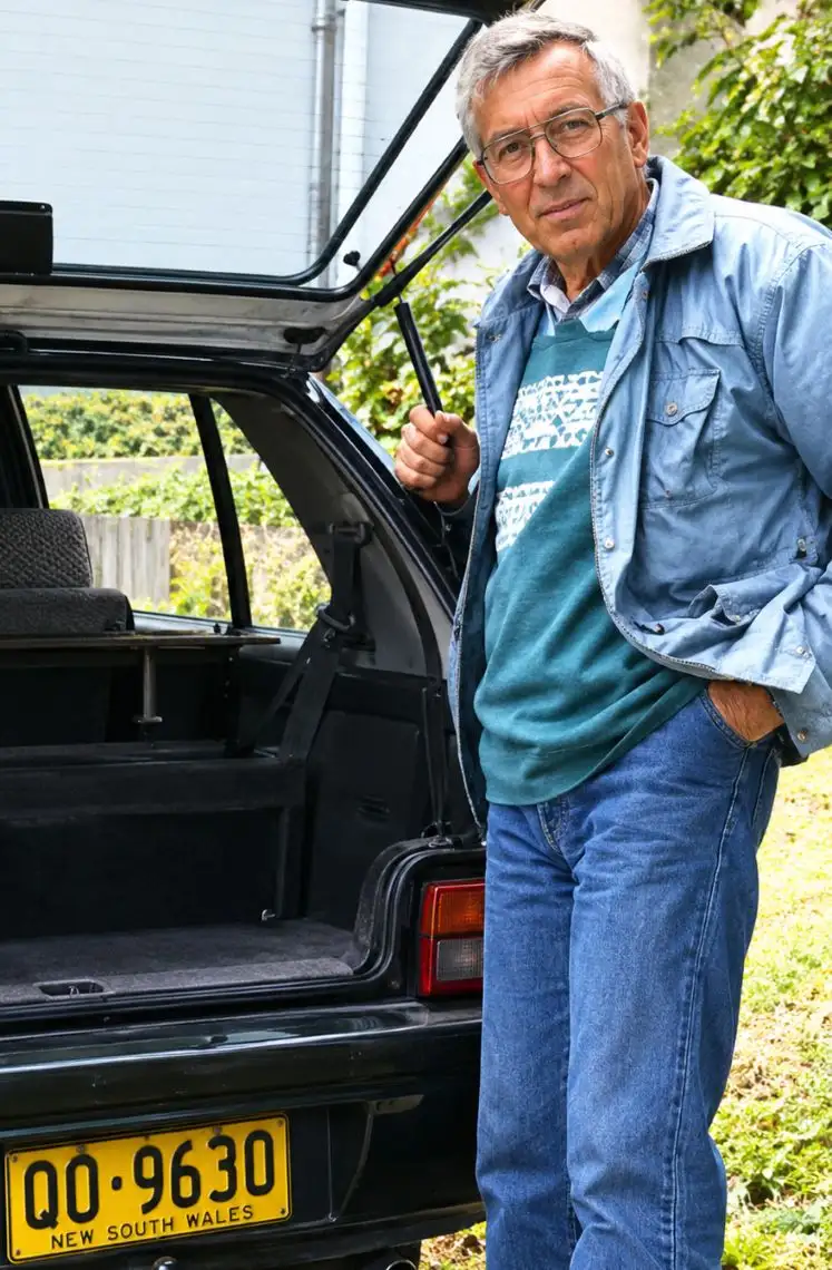
Des Clift, G3BAK (SK) who is credited as having the first UK 10 GHz contact with G3LZ in 1950.
The same issue of the Bulletin also details the 70 cm activity tests held in 1950. The reports read much like those for the 10 GHz activity days of the 1970s and '80s, which shows the state of the art on UHF at the time. G3APY was in the forefront of this work as well as of 10 GHz. The UK 70 cm record then stood at only 161 miles (259 km): dead easy now, but a milestone in 1950.
In the UK the 10 GHz band was developed by a small group of dedicated enthusiasts who built simple klystron transceivers using wideband FM. The most popular klystron of the 1960s and '70s was the 723A/B, identical in appearance to the 3 GHz 726A. These tubes were designed to work best at around 9.5 GHz, but amateurs found ways of "bending" them up into the lower 100 MHz of the band (the UK had 10.0 to 10.5 GHz available then). Output was a few milliwatts.
Klystrons and wideband FM
In the UK the 10 GHz band was developed by a small group of dedicated enthusiasts who built simple klystron transceivers using wideband FM. The most popular klystron of the 1960s and '70s was the 723A/B, identical in appearance to the 3 GHz 726A. These tubes were designed to work best at around 9.5 GHz, but amateurs found ways of "bending" them up into the lower 100 MHz of the band (the UK had 10.0 to 10.5 GHz available then). Output was a few milliwatts.
The klystron served as the oscillator on both transmit and receive, with the wideband FM applied to its repeller. It needed fairly high voltages by modern standards, up to 300 V or so. Portable supplies were usually 12 V DC input, 300 V DC output inverters, which often put a distinctive whine on the modulation. Many amateurs used directional couplers so the same oscillator could also act as the receiver local oscillator. Waveguide switches and other WG16 "plumbing" made these rigs bulky and off-putting to non-microwavers.
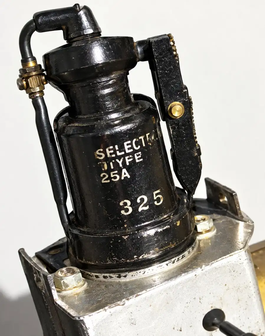
The klystron type 726A which is identical in appearance to the 723A/B.
Clive, GW4MBS mentions another klystron that found its way into amateur hands was the CV2346, a low-power reflex type made by EMI. It was designed for X band (8 to 10 GHz) and delivered around 50 mW into an external cavity formed by the two brass rings. It was widely used in Flann signal generators. The top cap is believed to be the repeller, which allows tuning via a 10-turn pot. As with the 723A/B, the cavity had to be distorted to get on band when centred on 10 GHz, and power fell off as a result.
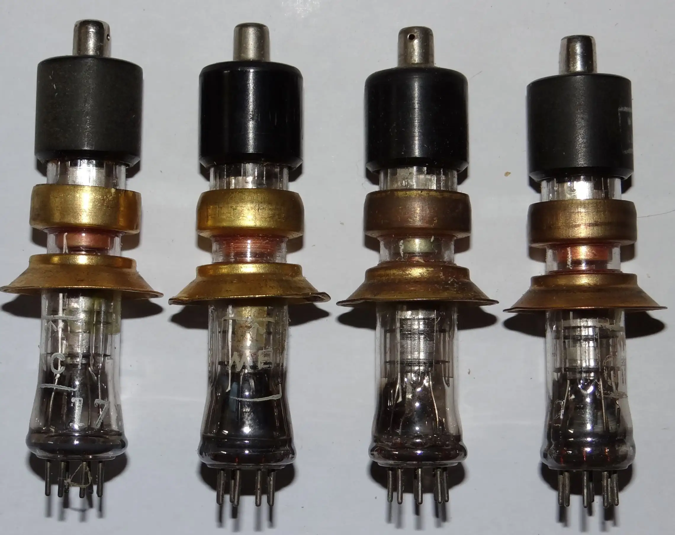
CV2346 reflex klystrons, which deliver around 50 mW into an external cavity formed by the two brass rings. Most amateurs favoured the 723A/B or KS9-20. Photo courtesy of Clive GW4MBS.
Duplex operation with a common IF of 30 MHz or 100 MHz (bandwidth around 200 kHz) was frequent. One station would transmit on, say, 10.100 GHz, and the other would set its local oscillator to 10.070 GHz (or 10.130 GHz) to hear the signal in a 30 MHz receiver. The first station, also with a 30 MHz receive IF, would hear the second at the same time. To find each other, each station modulated its transmitter with a 1 kHz tone; when the two stations were lined up the tones beat together in an unmistakable way. The receive front end was usually a simple diode such as the 1N23E.
In 1959, Bob, G3GNR, and Don, G3JHM, had their first 10 GHz QSO over a 4 km path between Worthing and Newhaven in Sussex (later extended to 30 km). They used the "evergreen" modified 723A/B on 10050 MHz at about 10 mW output, with power from two small rotary converters running off 12 V batteries. The receivers were single-ended mixers with LOs fed by a 10 dB directional coupler, and the measured noise figure was 11 dB. Both operators were still active on 10 GHz in the late 1990s and were probably among the longest-serving 10 GHz operators in the UK.
Equipment of this type enabled the 150 km "barrier" to be broken for the first time in the UK, when G3RPE and G3ZGO made contact between Dartmoor (SW England) and the Preseli Hills (SW Wales). That distance became the yardstick for 10 GHz performance, and the RSGB Microwave Distance Awards still recognise that level of achievement. It is easy now with modern narrowband gear, but it was quite difficult with the simple wideband equipment of the day.
Dain Evans, G3RPE, wrote the first microwave column in the RSGB's RadCom magazine, became chairman of the RSGB Microwave Committee and later RSGB Microwave Spectrum Manager. Until his untimely death he worked tirelessly for UK microwavers. He is remembered through the G3RPE Trophy, awarded to the leading station in the annual 10 GHz Cumulative Contests, formerly run by the RSGB and now by the UK Microwave Group.
The Americans put on the pressure
In 1960, W7JIP/7 and W7LHL/7 achieved a two-way 3 cm contact over 427 km. It was remarkable for the time and stood as the 10 GHz world record until 1976. Jimmy Oldaker, W7CQ, who read the original page, kindly sent a piece from QST of November 1960 showing W7LHL/7 in action on Green Mountain, Washington. Jimmy reported that Ernie, W7LHL, was still active on 10 GHz and building equipment for 24 GHz. Ernie regularly copied Jimmy's 240 mW 10 GHz beacon over a 349 km path with mountain ranges in between, which is definitely not line of sight. Many thanks to Jimmy for this piece of 10 GHz history.
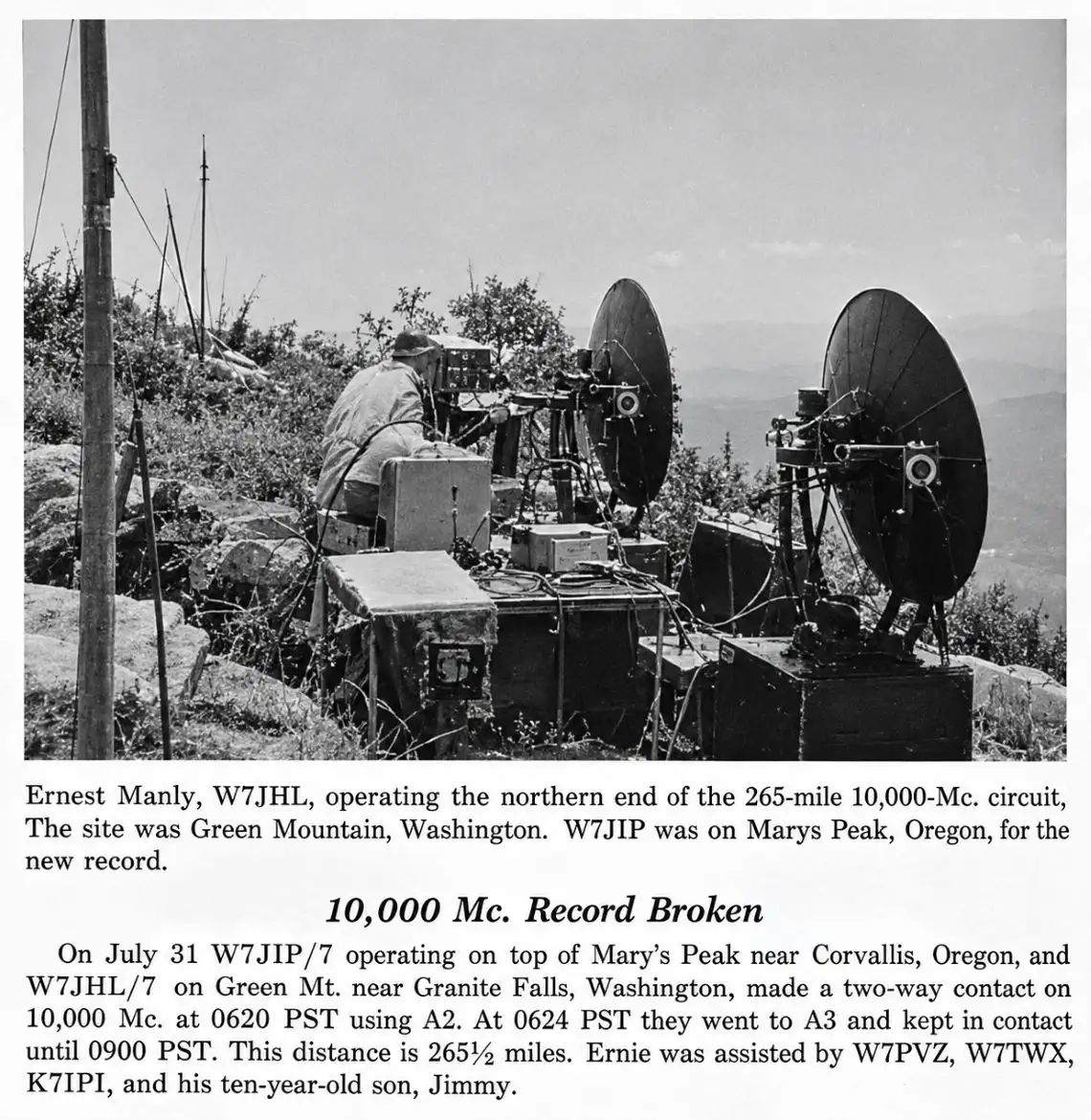
Cutting from QST magazine, November 1960.
Gunn diodes and new records
In the mid-1970s the Gunn diode appeared on the amateur market and revolutionised wideband operation. Power supplies shrank, because the Gunn needs only a low-current supply of around 7 V. The diodes themselves are only a few millimetres long, so 10 GHz equipment became highly portable. Many old timers still regard this as the "Golden Age" of 3 cm. Almost all active UK 10 GHz amateurs operated from portable sites, and the summer cumulative contests organised by the RSGB Microwave Committee became very popular. Hilltops in North Wales, the Pennines and the North and South Downs, among others, regularly "grew" tripods, dishes and 2 m talkback stations.
Peter, G3PHO developed a compact 3 cm transceiver based on a Gunn oscillator, a 1N23E receive mixer diode and a small solid-state 30 MHz IF with a 1.5 dB noise figure post-mixer amplifier. With an 18 inch (46 cm) dish, a short portable mast, an IC202S 2 m SSB handheld with a quarter-wave whip, and a small 12 V dry-fit battery, he often backpacked it up some of the country's highest mountains in search of longer line-of-sight paths (c.1984). Duplex operation remained the norm, as in klystron days, but 10.7 MHz IFs replaced 30 MHz in many cases.
The limits of the line-of-sight path became a challenge to 10 GHz operators.
Propagation studies and real 10 GHz DX
Excellent DX was worked with simple Gunn equipment. Operators such as GM3OXX/P, GW3PPF/P, GW4BRS/P, G3RPE and GM8BKE (now G8BKE), among many others, made contacts in the 1970s that would still give pleasure to narrowband operators today. The longest line-of-sight path worked was between the summit of Yr Wyddfa (Snowdon) in North Wales and Cairnsmore of Carsphairn in South West Scotland. At 245 km it was the best possible in the UK without enhanced propagation. Peter repeated the path in 1987.
Longer paths were worked thanks to the inquisitiveness of amateurs such as GW3PPF, who saw the potential of the moist air ducts that often form over the sea. He and others spent considerable time and money travelling the UK to establish these "super-refraction" paths, often hundreds of kilometres long. The longest of the 1970s, and a new world record, was on 14 August 1976 between Pendeen Sands, Cornwall, and Portpatrick in South West Scotland, a distance of 521 km. This exceeded the W7s' 1960 record by almost 100 km. G4BRS/P (the Barry Radio Society) and GM3OXX/P used simple 10 mW Gunn transceivers with small dishes (60 to 75 cm). Signals were exchanged directly on 10 GHz without prior 144 MHz talkback and peaked 45 dB above noise. A super-refractive sea duct carried them well beyond line of sight, and it was their ninth attempt at the record.
World records since then, whether wideband (by Italians) or narrowband (by Australians), have used the same super-refraction mode to exceed 1000 km. The current terrestrial world record is a staggering 2,732 km set on 5 January, 2015, by VK6DZ (operating portable at Torbay Hill, Western Australia) and VK7MO (operating portable at Cape Portland, Tasmania) across the Great Australian Bight using JT4f and SSB.
Halcyon days
The 1970s produced many UK 10 GHz "firsts". The first GW to GM contact took place in September 1973, when GW8CKT/P worked GM8AZU/P (now G4NNS). It was a world record at the time, exceeded a few months later by GM3OXX/P. Photographs of the GW and GM team carrying their gear, including an 80 cm dish, up Cairnsmore of Fleet appeared in The Short Wave Magazine in November, and is worth seeing if only for G8DKK's multi-coloured trousers.
The magazine says: equipment at both ends incorporated a CXY19 Gunn oscillator with about 100 mW output. Their antenna was a 32 inch (~80 cm) dish with a horn feed. Talkback between the summits was on 2 m, and base stations kept in contact on 80 m.
The GW side
At the other end of the 3cm GW-GM first was G8HCO, G8BPN and G8FTB who formed the the GW team on the summit of Yr Wyddfa (Snowdon) and used the callsign GW8CKT/P. Their antenna was a small horn (held by G8FTB) because of strong winds at the summit. Their gear was humped to the summit on foot after the train service was cancelled due to the dreadful weather. At 212 km, this set a new British record at the time.
The first G to PA contact was made on 3 August 1975 by G8APP/P and PA0KKZ, who covered 240 km with 20 mW (klystron) and 3 mW respectively. Both stations were at or near sea level. It followed a one-way attempt by G4ALN, who used 10 mW into a dustbin lid as an antenna. G8APP/P was at Walton-on-the-Naze, a site famous in UK 10 GHz history and still used by the UHF/microwave contest group G0VHF. It is arguably the finest portable location in the UK for working the European continent.
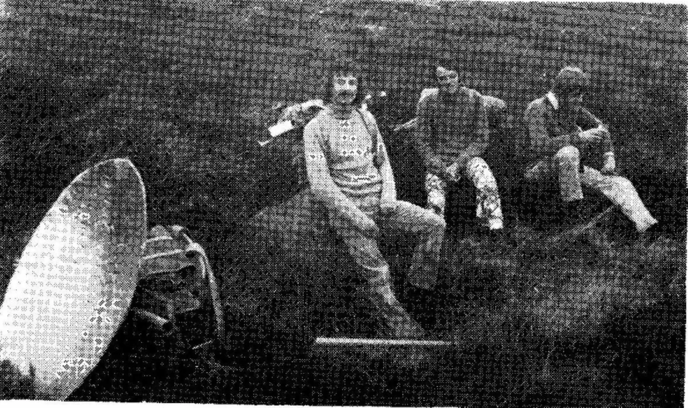
The Shortwave Magazine, November 1973: The GM8AZU/P group on their way up Cairnsmore of Fleet. Seen in the photo are G8APZ, G8DKK and G8AMG.
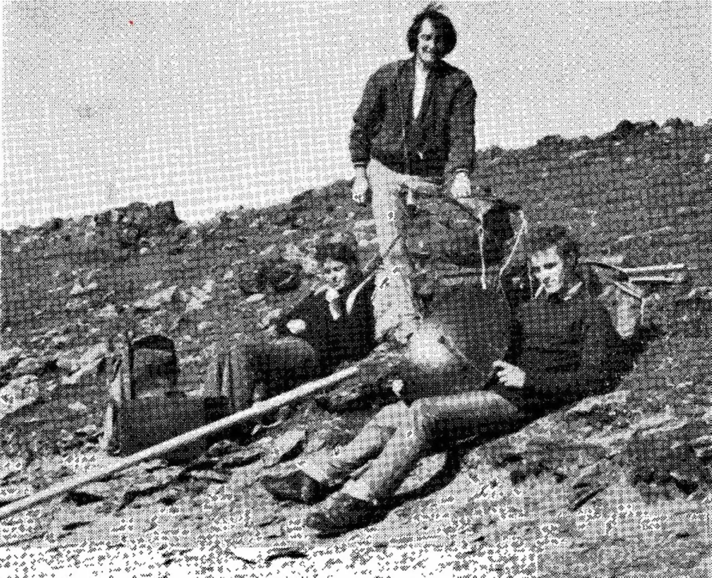
The GW8CKT/P team on the way to the summit of Yr Wyddfa (Snowdon) for their 3 cm attempt with GM8AZU/P , Left to right: G8HCO, G8BPN and G8FTB.
By November 1976, 12 countries had been worked by G stations. The first GI to GM contact was made in August 1976. Germany, Denmark, Norway and Sweden were still awaiting contact.
Narrowband developments
Throughout the wideband period, a small group of British amateurs was developing crystal-controlled narrowband systems for 10 GHz. These typically used a VHF crystal oscillator, in some cases with watts of output, driving a chain of varactor diode multipliers. The chain provided narrowband transmitter RF (CW and narrowband FM) and local oscillator drive for simple diode mixer receivers. No transistors then available would work as amplifiers or mixers at 10 GHz.
The best-known team was G3BNL and G3EEZ. Les and Alan built remarkable narrowband systems that were used to set UK records on all the microwave bands of the day. G3BNL is now a Silent Key and greatly missed; his name lives on in the G3BNL Trophy, awarded annually for expertise and innovation in home construction.
Clive Elliott, GW4MBS, who worked G3BNL and G3EEZ regularly, feels that G3BNL's role deserves much more credit. As Clive recalls, Les Sharrock G3BNL was the instigator of narrowband operation (CW and narrowband FM) on the microwave bands, long before SSB and the JVL transverters arrived. Clive saw his techniques demonstrated at a VHF Convention in the early 1970s and was inspired by them. The system was to build a transmitter for 1152 MHz and multiply it up with varactors, using the many surplus Mullard varactors that could be had for as little as £1:
As Clive remembers it, those multiples were the basis of narrowband activity for many years, although changes to the amateur allocations mean that many of the frequencies have since moved. When G3EEZ passed away, Clive took over as G3BNL's regular partner, because so few others were on narrowband. He adds that in some quarters narrowband was despised for destroying the simplicity of wideband operation with Gunn devices, and that the schism went so far that 10 GHz contests were run with separate sections for the two incompatible kinds of equipment.
Another pioneer was Mike Walters, G3JVL. While Gunn wideband was at its most popular, Mike experimented with image-recovery and narrowband filter systems, leading to the "JVL rig". A step-recovery diode multiplier in WG16, driven by a crystal oscillator (typically 384 MHz at about 500 mW), produced 5 to 10 mW at 10224 MHz. This passed through a narrow waveguide filter, the secret of the rig's success: its three iris-coupled cavities reduced the image to negligible levels. The filtered 10224 MHz then drove an in-line waveguide diode mixer, to which a few milliwatts of 144 MHz was applied.
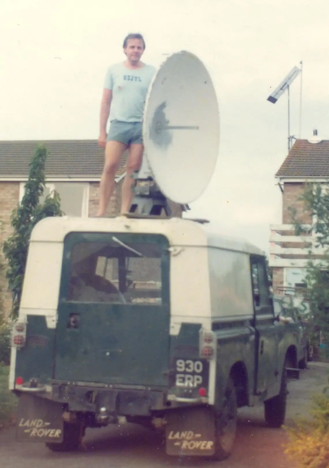
Mike Walters G3JVL (SK) in July 1979 on the roof of his Landrover with his 10 GHz dish. Photo Courtesy G3JVL.
The resulting 10368 MHz SSB/CW signal passed through a second three-stage iris-coupled filter to give around 1 mW at the antenna port. The JVL rig was therefore a complete transceiver. As a receiver it held its own: thanks to its excellent image rejection, noise figures of 6 to 7 dB were possible with a bare diode mixer, and without a GaAsFET preamp in sight.
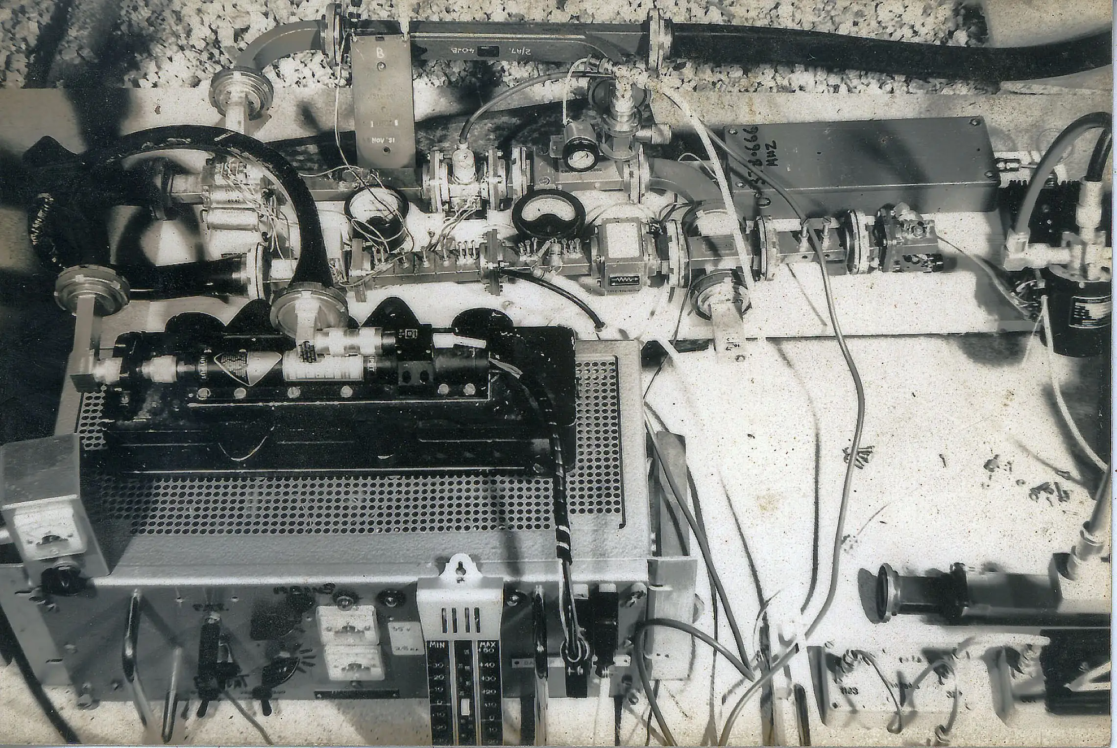
In foreground EHT PSU for Litton TWT bolted on top. Behind is the JVL 10GHz transverter.
Photo Courtesy of Clive GW4MBS.
This rig let many UK amateurs taste 10 GHz narrowband for the first time. Unless you had a TWT amplifier, though, its 0.5 to 1 mW output was little better than the wideband rigs of the day, although Peter does say he worked several obstructed paths with his JVL that Gunn equipment could not manage.
Mike's work did not stop there. As Clive GW4MBS recalls, the 10 GHz transverter design was also scaled up into WG14 for 5.7 GHz, and Mike and Julian Gannaway, G3YGF, carried out pioneering tropospheric scatter trials.
Something was needed to raise output into the tens of milliwatts: the GaAsFET.
GaAsFETs, G4DDK and G3WDG
In the mid to late 1980s a number of German solid-state, GaAsFET-based designs appeared in the UK. A commercial transceiver from SSB Products retailed at over £400, and many amateurs thought the dreaded "black box" had finally reached microwaves. However, the microwave bands attract amateurs who have tired of the commercial-equipment approach to the hobby, and only a few SSB Products systems were sold.
Meanwhile Sam Jewell, G4DDK, was developing a series of compact local oscillator PCB designs for the 1 GHz region. In March 1987 the RSGB Microwave Newsletter published the DDK001, "A Local Oscillator Source for 1152 MHz", followed by the DDK002 1 W amplifier. Built into modules, these offered a reliable narrowband route to 23 cm and a basis for transverters to the higher bands. Sam then introduced the DDK004, giving 10 to 12 mW at around 2.5 GHz.
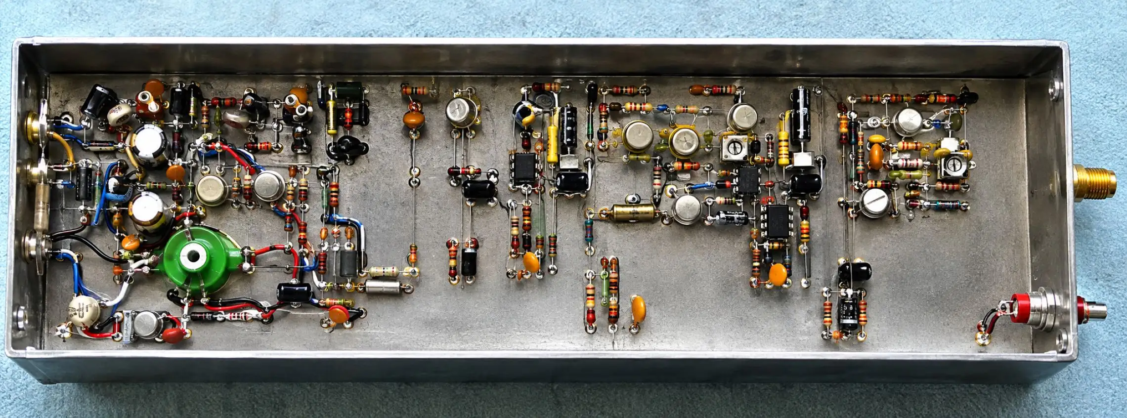
G4DDK Source for 2.4-2.6 GHz
This had a profound effect on UK 10 GHz narrowband. At the same time, Charlie Suckling, G3WDG, was working on a 10 GHz transverter system that would bring SSB/CW to all UK 10 GHz operators, and which virtually killed off wideband FM as the preferred mode. His designs use the G4DDK driver modules to feed a transmit multiplier/amplifier and a receiver, each using cheap, readily available GaAsFETs. They offered what was, in 1990, high power (50 to 100 mW) and low-noise reception (around 2 to 3 dB). As if by fate, a large quantity of cheap (about £2 each) 10 GHz GaAsFETs reached the surplus market just as Charlie was developing his system. The supplier, J. Birkett of Lincoln, and the devices' code names "Red Spot" and "Black Spot" became by-words in the UK microwaver's vocabulary. The WDG kits soon became the most widespread 3 cm equipment in the UK.
A basic WDG transverter for 10 GHz uses a WDG001 ×4 multiplier/amplifier, a WDG002 receive converter and a WDG003 transmit downconverter. The DDK004 source at 2.5 GHz drives both local oscillators. Complete transceiver operation needs only a low-power 144 MHz transceiver such as the IC202 or FT290, a microwave coaxial relay and a +12 V DC supply. The modules are built in small tinplate boxes (the WDG001 is on Teflon PCB in a box 11 cm × 3.5 cm × 3 cm), which gives very efficient shielding and PCB mounting, and are fully connectorised in SMA. Charlie later added modules including a 1 W PA and a sub-2 dB HEMT receive preamp.
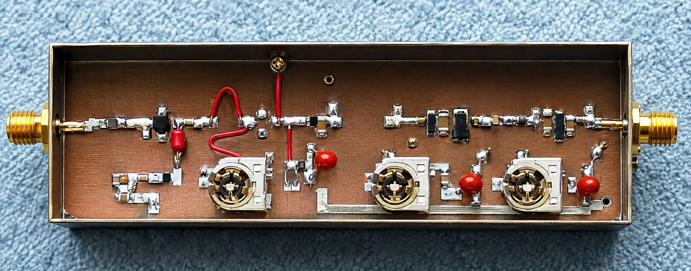
A partially completed G3WDG001 10GHz x4 multiplier / amplifier
These kits and many others, including designs for 23 cm and 13 cm, were available at the time from the Microwave Components Service, operated by Petra Suckling, G4KGC, Charlie's wife.
Charlie also proved how good his equipment was: in 1995 he made the first UK to Australia EME (Earth-Moon-Earth) contact, working Lyle Patison, VK2ALU, of Wollongong, New South Wales. WDG equipment was in use at both ends.
The early 1990s: the "White Box"
In the early 1990s a number of surplus M/A-COM 10.5 GHz data-link transceivers reached the UK surplus market. Nicknamed the "White Box", it sold for around £100, quite cheap for a 200 mW transceiver. G3PHO and G8AGN were in the forefront of the White Box conversion and in the end, dozens were modified by UK amateurs. They often formed the heart of a home or portable station and were used in some microwave beacons. Modification details were already available from the USA, where White Boxes appeared in their hundreds, particularly on the West Coast, and further modifications were developed in the UK. G3WDG's WDG005 receive preamp fits neatly inside, improving the "barefoot" ring mixer's 11 dB noise figure to around 2 to 3 dB, and the WDG HEMT preamp can bring it down towards 1 dB. The White Box was the basis of Peter's own 10 GHz system in those days and is still occasionally used for both home and portable operation.
The late 1990s to the early 21st century
The G3WDG/G4DDK systems led to more and more home-station operating in the UK. Cheap (sometimes free) 4 to 5 W travelling wave tube (TWT) amplifiers became available during the 1990s and were easily driven by a couple of milliwatts. Higher powers were around too, with quite a few UK amateurs running over 10 W and one or two around 60 W.
In the latter half of the 1990s a series of excellent kitsets, including complete transverters, oscillator/multipliers and power amplifiers, reached the European market. They are produced in Germany by three main companies: Eisch Electronic, Kuhne Electronic (DB6NT) and Philip Prinz (DL2AM). Michael, DB6NT, and Kuhne Electronic have changed the face of amateur microwaves, certainly in Europe if not the world, supplying kits and ready-made equipment from 1.2 GHz well into the sub-millimetre bands at affordable prices and excellent quality. Few active European microwavers do not have at least one DB6NT item in the shack, and Peter's own equipment is based largely on DB6NT transverter kits. In the USA, Down East Microwave has grown into that continent's major supplier, with many original US designs.
Between 1978 and 31 October 1981, Mike Walters, G3JVL, on Hayling Island, and Julian Gannaway, G3YGF, at Oxford University, sent regular narrowband signals to each other on 10 GHz. As Clive recalls, G3JVL sent a beacon every day with a 10 W TWT, and Julian checked regularly for an incoming signal. When an enhancement was seen at Oxford, a quick phone call started a QSO. Julian's paper describing the mechanisms of tropospheric scatter, and how to calculate path loss for the mode, was published in RadCom in August 1981. Clive lived directly under the path, so there was always something to listen for, although what he heard was often very weak.
Hayling Island to Oxford: the tropo scatter trials
Between 1978 and 31 October 1981, Mike Walters, G3JVL, on Hayling Island, and Julian Gannaway, G3YGF, at Oxford University, sent regular narrowband signals to each other on 10 GHz. As Clive recalls, G3JVL sent a beacon every day with a 10 W TWT, and Julian checked regularly for an incoming signal. When an enhancement was seen at Oxford, a quick phone call started a QSO. Julian's paper describing the mechanisms of tropospheric scatter, and how to calculate path loss for the mode, was published in RadCom in August 1981. Clive lived directly under the path, so there was always something to listen for, although what he heard was often very weak.
Clive has replotted the path from the data in Julian's paper. With high-gain antennas, beamwidths of 4° at G3JVL and 2° at G3YGF give quite a small common volume, which is line of sight to both stations. The hope is that within it there will be scatter from dust particles, clouds and variations in refractive index in the atmosphere at heights of about 300 m to 15 km above sea level. Each extra degree of elevation adds about 10 dB of path loss. As Clive notes, G3JVL showed that height is not the most important feature of a good site: a good run at a distant horizon matters more.
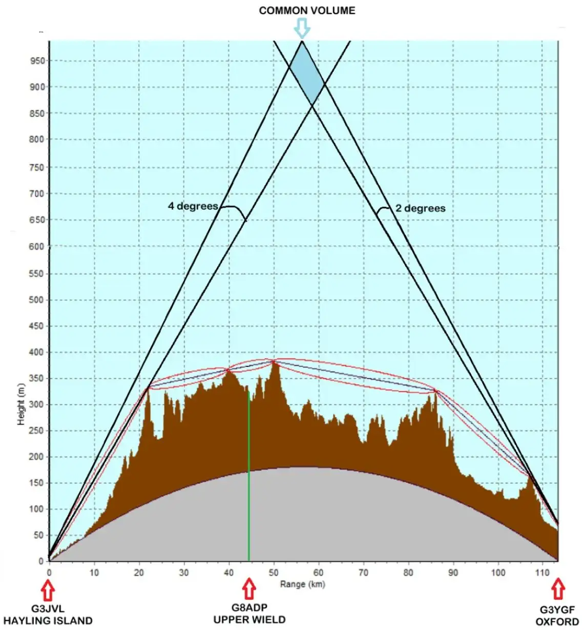
Clive's plot of the Hayling Island to Oxford path, showing the common volume. Credit Clive GW4MBS.
Julian's station
Dr. Julian Gannaway's station used a 4 ft (1.2 m) dish in the lift room on the top floor of the Engineering Science building, about 30 m (100 ft) above the ground, operating through a window. Clive points out that this avoids the difficulties of an external dish, and keeps the equipment warm and out of the weather.
He adds that indoor dishes were nothing new: several WW2 stations did propagation studies on 3, 6 and 9 cm across Cardigan Bay and up the Irish Sea from small buildings with large windows.
Clive's lesson, which he still feels is missed, is that many operators peak the elevation on a signal and assume that is all there is to it, without looking for the common volume high in the troposphere. When setting limits of elevation for any mast mounted dish design, he suggests allowing a large arc, not only to look for ground and Sun noise but also for clouds and beyond into the troposphere.
Rain scatter and the first CW QSO
From November 1979 Clive listened for the GB3SWH beacon at Bushey. It was detectable a few miles from home in Upper Wield, near Alton in Hampshire, but rarely heard it. He began to suspect that rain sometimes helped a path. He remembers being told firmly at a Microwave Round Table by a microwave engineer that the professionals knew about the effects of rain, but that it had no place in amateur communication and he was simply wasting his time. He had by then very convincing examples of rain enhancement, so he wrote to Pat Hawker, G3VA, who wrote the amateur radio page in Wireless World.
In the March 1981 issue, in his "World of Amateur Radio" column under the heading "Using rain on 10 GHz", Hawker covered the contents of Clive's letter. Clive was then G8ADP, in a heavily screened location at Alresford, Hampshire. The column said that he could work regularly over paths of up to 150 km by tropo scatter, and was convinced that signals were often enhanced by rain scatter.
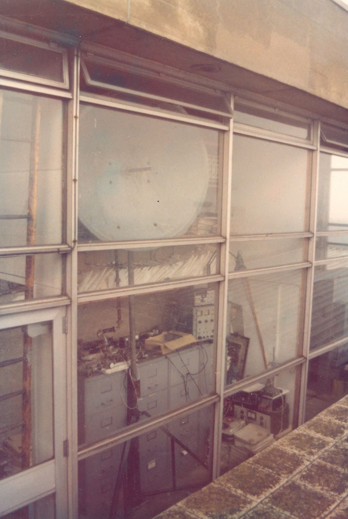
G3YGF's (SK) 1.2 m dish behind a window in the lift room on the top floor of the Engineering Science building. Photo courtesy of Dr. Julian Gannaway, G3YGF.
Over a difficult 40 km path to G3JVL, who was at sea level near Portsmouth, effective contacts depended largely on rain scatter. Signals peaked when there was heavy rain virtually overhead (drizzle was not enough), and G3JVL could often be received whichever way Clive's antenna was pointing. The column gave G3JVL's normal signal as about -6 dBm in a 2.5 kHz bandwidth, rising to 30 dBm in heavy rain, or about 5 to 15 dBm with the antenna pointing in other directions, including straight up. It added that Clive felt this form of over-the-horizon 10 GHz propagation was still seldom recognised or used, because so much effort went into portable operation in conditions where heavy rain was not welcome.
Clive adds that during the JVL rain scatter tests, signals could be heard on open waveguide and were no stronger on a high-gain dish or "fly swatter" antenna. The clarity of the signal, however, was far better with the narrow beam.
Strong rain scatter openings were great fun, especially in front of non-believers, but regular tropo scatter signals were very weak. On Julian's advice Clive could see the value of CW, but as a Class B licensee he was not allowed to use it. So, with a bit of effort, he took to the air for the first time as G4MBS in June 1981, and to prove the value of the mode, his first QSO was a weak CW exchange with G3YGF at Oxford on 10 GHz tropo scatter. His last 10 GHz QSO from Upper Wield was with G3WDG in June 1985.
Where next?
Peter's original was written in 2005 and partly updated in 2020. This section has been brought up to date.
There are now ready built transverters available from Kuhne Alaris in Germany, Down East Microwave in the US and OK1FPC in Czech republic as well as designs that can be built from W1GHZ, G4HSK, F6BVA, F1JGP and VE2ZAZ. There is a wide variety of solid-state power amplifiers (SSPAs) made for the amateur microwave market. Over 50 W is available on 10 GHz (at a price). With higher power levels and home-station operating have allowed unusual propagation modes such as rainscatter, aircraft scatter (reflection), troposcatter and ducting to be used to work very long paths in the UK and across the sea to Europe.
"Entry level" 10 GHz narrowband power of 1 W is now de rigueur. In the UK, the 60 to 90 cm offset-fed dish (often ex-satellite TV) is the most popular antenna, and contacts up to 400 km are the norm. Some home stations work daily skeds over such distances, with 800 to 1000 km+ contacts when tropo conditions are good. During the monthly contest weekends, when activity is at its highest, portable stations often work long distances on narrowband, sometimes beyond 600 km under apparently flat band conditions, usually through aircraft and rainscatter. Despite the growth of home stations, portable operation remains popular, as any Cumulative Contest weekend shows.
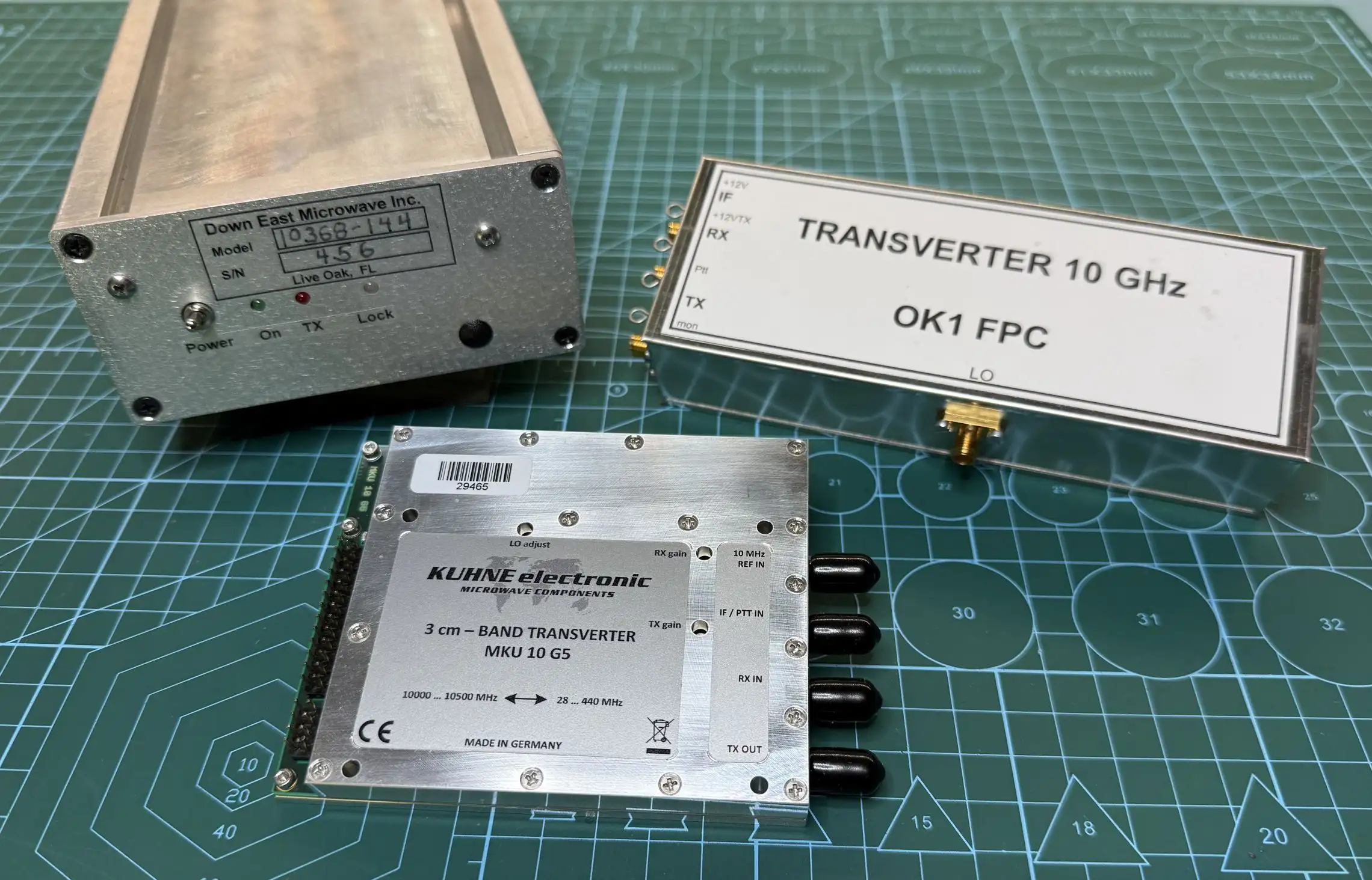
Modern 10GHz Transverters from Down East Microwave, Kuhne Electronic and OK1FPC.
EME is now quite common on 10 GHz, and a number of UK operators can make overseas contacts via the Moon. Software that keeps the large dish on target and exchanges contact details by data mode, often at or below the limit of the human ear, has made this a little "easier".
The 24 GHz band is now going through the kind of revolution that 10 GHz saw a decade or so earlier. Narrowband and "high" power (2 W) have arrived at 24 GHz, and surplus Wavelab "boxes" are changing that band too. But that is another story.
10 GHz may have become "old hat" for some, but there is still plenty to do there and room for more converts to microwaves.